Showing posts with label drawing. Show all posts

Tuesday, November 29, 2011

How to Modify SolidWorks Hole Callouts


This video shows you how to modify the Hole Callout formats when adding callouts to holes in your drawing documents.

For a list of all Hole Callout variables, refer to the Help file.

Tuesday, November 8, 2011

Hole Table Padding - Adjusting beyond the standard limits

When adding Hole Tables to drawings the table often extends, vertically, beyond the limits or boundaries of the specified sheet size (see Pic_1). You may have tried to adjust the table font size and zeroed the Vertical Cell Padding dial to rectify this, but noticed that even though the padding dial is zeroed, there is still an amount of padding that remains around the text. This remaining padding takes up valuable space, let's see how we can reduce/shrink this cell padding to tightly hug the cell boundary.

Pic
_1: The Problem
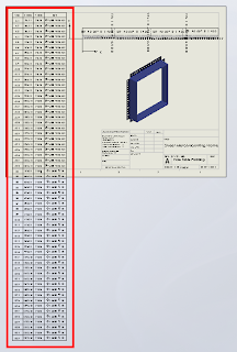
Before we continue, remember that we can only fit so much on to a single sheet before it becomes unreadable, so there is obvioulsy a limit to how many rows you will be able to fit vertically on a specific sheet size.

Click anywhere in the table to activate its properties. You will see this dialogue appear above the table:


Note where the adjustment settings are for Font Size and Vertical Cell Padding. We'll get back to that in a second.

Next, click on the number 2 to select the entire row. Hold down the Shift key and select the last row in your table (I had sixty rows all up in this example). You should now have all rows except the heading row selected. With all rows selected you can change your font size; I have used 9, which is still quite readable and then we want to adjust the Vertical Cell Padding.

You will note though, that when you dial down (using the up-down arrow toggles) you will be stopped at zero. Naturally you will think this to be the limit, but alas, we know with Solidworks anything is possible. Simply select the Vertical Cell Padding field as below...


Type negative 1.8 i.e. -1.8 and hit the Enter key on your keyboard. You should now be looking something like this in the settings dialogue...


and your cell text will be hugging the cell borders all nice and cosy, like this:


And while we are at it, quickly click anywhere in the table, then click the black cross to the left of Column A to activate the table properties dialogue, which will appear to the left of your screen. We want to tidy things up a little before printing. In the properties dialogue select "Combine same sizes" and you will get this:


In the properties dialogue, click the green check mark to close and we're done.


You should now have your table fitting nicely onto your drawing sheet and looking much better than when we started.


Have a play with those settings and I hope that this has helped you somewhat to tidy up those Hole Tables.

Sunday, May 22, 2011

Printing Drawings in colour using CutePDF


Colour can be used to good effect in drawings to increase clarity - for example by differentiating between dimension lines, model lines and annotations. Under Document Properties, you can assign new annotations to different layers, and assign colours per layer.

However, when it comes time to print, sometimes it’s difficult to get those colours to come through in the printout. Here’s how to do it with CutePDF Writer, a program which emulates a printer in Windows, but creates a PDF file rather than a physical print out.

Firstly, download and install CutePDF Writer: http://www.cutepdf.com/

From your SolidWorks drawing:
  1. File >> Page Setup >> set Drawing Colour to Color/Gray Scale >> OK
  2. File >> Print... >> select CutePDF Writer as the printer >> Properties >> Advanced (bottom right on the Paper/Quality tab)
  3. Graphic >> Image Color Management >> click on ICM Method >> select “ICM handled by Host System” >> OK >> OK
  4. Set your other print options and then print. You will be prompted to save the drawing as a PDF file on your computer.
If you are having trouble physically printing a drawing in colour, try printing it to PDF as above then printing the PDF. Alternatively, when printing, select your printer >> Properties, and locate the option that tells the printer to allow SolidWorks to handle the colour. Since each printer driver is different, you may need to refer to your printer manual or the manufacturers website to find the correct option.

Sunday, May 15, 2011

Documenting Part Configurations in a Drawing


This video shows you one way to document a number of different part configurations on the same drawing, using Custom Properties to capture the dimensions that change across the configurations, and a BOM in a drawing to display those dimensions.

Monday, March 28, 2011

Configuring the SolidWorks Toolbox


The SolidWorks Toolbox is a database of commonly used fasteners and parts, available if you have SolidWorks Professional or Premium. You can customise the Toolbox with your own part numbers, descriptions and other fields you may wish to show on a Bill Of Materials.

This video shows you how to customise the Toolbox to reflect the fasteners you use in your designs, and how to quickly add a large number of properties to those parts using Microsoft Excel.

The Toolbox runs off a database which contains all of the available sizes and dimensions for each part it contains. When you select a certain component for the first time in SolidWorks, it generates that particular configuration or part based on the dimensions contained in the database. If you wish to change the size of an existing Toolbox component, and the new size has not been used before, you need to RMB on the part (on-screen or in the Feature Tree) and select “Edit Toolbox Definition”. This will open the same original Toolbox Property Manager box, and generate the new config when you press OK.

Alternatively, from the Toolbox Configuration window, from the same button where you export settings to Excel, you can choose to "Create configurations" to generate all configurations for the component. This means you can use the ordinary method of changing configs in the assembly. But be careful using this – I did it on the bolt in the video with 198 configs and the result was a 25Mb part file. If you choose to do this, make sure you remove unnecessary bolt sizes and lengths first - you can always add them back in later.