

This video shows you how to use custom Decals in SolidWorks 2012.
Popular Posts
-
 Disney cars Disney Cars Saly Filmore Disney Cars coloring pages wallpaper Lightning Mcqueen Ramone disney cars poster
 -
 2013 Cars Model, 2013 car, photo mercedes, car dekho, car electric, new cars, new vehicle, cost of cars...
 -
 Red And Black Ferrari Car Red Ferrari Car Wallpaper Yellow Ferrari Car Picture Latest Model Ferrari Car Pink Ferrari Car Wallpaper
Showing posts with label appearance. Show all posts
Showing posts with label appearance. Show all posts
Wednesday, February 1, 2012
Tuesday, November 8, 2011
Hole Table Padding - Adjusting beyond the standard limits
When adding Hole Tables to drawings the table often extends, vertically, beyond the limits or boundaries of the specified sheet size (see Pic_1). You may have tried to adjust the table font size and zeroed the Vertical Cell Padding dial to rectify this, but noticed that even though the padding dial is zeroed, there is still an amount of padding that remains around the text. This remaining padding takes up valuable space, let's see how we can reduce/shrink this cell padding to tightly hug the cell boundary.
Pic_1: The Problem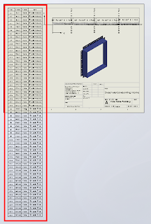
Before we continue, remember that we can only fit so much on to a single sheet before it becomes unreadable, so there is obvioulsy a limit to how many rows you will be able to fit vertically on a specific sheet size.
Click anywhere in the table to activate its properties. You will see this dialogue appear above the table:

Note where the adjustment settings are for Font Size and Vertical Cell Padding. We'll get back to that in a second.
Next, click on the number 2 to select the entire row. Hold down the Shift key and select the last row in your table (I had sixty rows all up in this example). You should now have all rows except the heading row selected. With all rows selected you can change your font size; I have used 9, which is still quite readable and then we want to adjust the Vertical Cell Padding.
You will note though, that when you dial down (using the up-down arrow toggles) you will be stopped at zero. Naturally you will think this to be the limit, but alas, we know with Solidworks anything is possible. Simply select the Vertical Cell Padding field as below...

And while we are at it, quickly click anywhere in the table, then click the black cross to the left of Column A to activate the table properties dialogue, which will appear to the left of your screen. We want to tidy things up a little before printing. In the properties dialogue select "Combine same sizes" and you will get this:

In the properties dialogue, click the green check mark to close and we're done.
You should now have your table fitting nicely onto your drawing sheet and looking much better than when we started.

Have a play with those settings and I hope that this has helped you somewhat to tidy up those Hole Tables.
Pic_1: The Problem

Before we continue, remember that we can only fit so much on to a single sheet before it becomes unreadable, so there is obvioulsy a limit to how many rows you will be able to fit vertically on a specific sheet size.
Click anywhere in the table to activate its properties. You will see this dialogue appear above the table:

Note where the adjustment settings are for Font Size and Vertical Cell Padding. We'll get back to that in a second.
Next, click on the number 2 to select the entire row. Hold down the Shift key and select the last row in your table (I had sixty rows all up in this example). You should now have all rows except the heading row selected. With all rows selected you can change your font size; I have used 9, which is still quite readable and then we want to adjust the Vertical Cell Padding.
You will note though, that when you dial down (using the up-down arrow toggles) you will be stopped at zero. Naturally you will think this to be the limit, but alas, we know with Solidworks anything is possible. Simply select the Vertical Cell Padding field as below...

Type negative 1.8 i.e. -1.8 and hit the Enter key on your keyboard. You should now be looking something like this in the settings dialogue...


and your cell text will be hugging the cell borders all nice and cosy, like this:


And while we are at it, quickly click anywhere in the table, then click the black cross to the left of Column A to activate the table properties dialogue, which will appear to the left of your screen. We want to tidy things up a little before printing. In the properties dialogue select "Combine same sizes" and you will get this:

In the properties dialogue, click the green check mark to close and we're done.
You should now have your table fitting nicely onto your drawing sheet and looking much better than when we started.

Have a play with those settings and I hope that this has helped you somewhat to tidy up those Hole Tables.
Sunday, April 17, 2011
HDR Environment images in PhotoView 360
PhotoView 360 uses HDR Environment images to create photorealistic renders. This video explains what these images are, and why they are the default method for lighting scenes in PhotView 360.
These HDR Environment images can be broken down into two components:
- The Environment, which is a 360degree panorama of a scene, which is reflected by the model you are rendering.
- The High Dynamic Range (HDR) image format, which captures more information per pixel than a standard image file, which provides PhotoView 360 with accurate lighting information for the scene
You can find all of the default PhotoView 360 HDR Environment images and backgrounds under [Program Files]\SolidWorks Corp\SolidWorks\data\Images\textures\background, where
While the Basic scenes provide a range of generic photo studio environment images that create clean-looking renders, if you want to create interesting reflections, or an “in-context” shot of your product sitting in front of a realistic scene, you should consider using a custom Environment image that matches the model – e.g. a model of a car should use a road or car park scene, not a kitchen scene.
There are a huge number of resources on the internet for HDR Environment images that cover as many different scenes as you can imagine, most of which you can use in PhotoView 360:
Free HDR resources (not all products listed may be free):
HDR resources that you must buy to use:
- http://www.doschdesign.com/products/hdri
- http://www.3sixo.net/3sixo_categories.php
- http://www.aversis.be/hdri/
- http://www.lightworks-user.com/hdri_starter_collection.htm
- http://www.sachform.de/
You can find many more HDR Environment image resources, plus detailed instructions for creating your own, simply by searching online.
Once you have your custom HDR Environment image downloaded, you can load it in PhotoView 360 through Display Manager tab >> RMB Scene >> Edit Scene >> Environment >> Browse... to the image location. Then rotate it to suit the model, adjust the floor options, alter the brightness and if you add any SolidWorks lights, you can save the whole shebang as a custom scene file for later use under the Advanced tab in Edit Scene.
Happy rendering!
Subscribe to:
Posts (Atom)
Hot Posts

Hot Car Girl
