

This is a brief overview of Solidworks drawing views and the associativity between parts, assemblies and their drawings.
Popular Posts
-
 Disney cars Disney Cars Saly Filmore Disney Cars coloring pages wallpaper Lightning Mcqueen Ramone disney cars poster
 -
 2013 Cars Model, 2013 car, photo mercedes, car dekho, car electric, new cars, new vehicle, cost of cars...
 -
 Red And Black Ferrari Car Red Ferrari Car Wallpaper Yellow Ferrari Car Picture Latest Model Ferrari Car Pink Ferrari Car Wallpaper
Showing posts with label tutorial. Show all posts
Showing posts with label tutorial. Show all posts
Tuesday, February 28, 2012
Tuesday, February 7, 2012
Wednesday, February 1, 2012
Tuesday, January 24, 2012
SolidWorks Feature Statistics
This video shows how to use SolidWorks Feature Statistics to evaluate how long each feature takes to rebuild so you can make an informed decision about which features need to be modified or suppressed in order to decrease rebuild time.
This file used in this video was supplied by Xped
Tuesday, January 10, 2012
How to install Multiple SolidWorks versions on one Computer
The method used will help keep the file references between the two versions apart.
Tuesday, December 13, 2011
How to determine the Volume of a Shell Feature in SolidWorks
Demo video that demonstrates how to determine the volume of a shell feature in Solidworks.
Tuesday, November 8, 2011
Hole Table Padding - Adjusting beyond the standard limits
When adding Hole Tables to drawings the table often extends, vertically, beyond the limits or boundaries of the specified sheet size (see Pic_1). You may have tried to adjust the table font size and zeroed the Vertical Cell Padding dial to rectify this, but noticed that even though the padding dial is zeroed, there is still an amount of padding that remains around the text. This remaining padding takes up valuable space, let's see how we can reduce/shrink this cell padding to tightly hug the cell boundary.
Pic_1: The Problem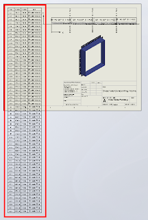
Before we continue, remember that we can only fit so much on to a single sheet before it becomes unreadable, so there is obvioulsy a limit to how many rows you will be able to fit vertically on a specific sheet size.
Click anywhere in the table to activate its properties. You will see this dialogue appear above the table:

Note where the adjustment settings are for Font Size and Vertical Cell Padding. We'll get back to that in a second.
Next, click on the number 2 to select the entire row. Hold down the Shift key and select the last row in your table (I had sixty rows all up in this example). You should now have all rows except the heading row selected. With all rows selected you can change your font size; I have used 9, which is still quite readable and then we want to adjust the Vertical Cell Padding.
You will note though, that when you dial down (using the up-down arrow toggles) you will be stopped at zero. Naturally you will think this to be the limit, but alas, we know with Solidworks anything is possible. Simply select the Vertical Cell Padding field as below...

And while we are at it, quickly click anywhere in the table, then click the black cross to the left of Column A to activate the table properties dialogue, which will appear to the left of your screen. We want to tidy things up a little before printing. In the properties dialogue select "Combine same sizes" and you will get this:

In the properties dialogue, click the green check mark to close and we're done.
You should now have your table fitting nicely onto your drawing sheet and looking much better than when we started.

Have a play with those settings and I hope that this has helped you somewhat to tidy up those Hole Tables.
Pic_1: The Problem

Before we continue, remember that we can only fit so much on to a single sheet before it becomes unreadable, so there is obvioulsy a limit to how many rows you will be able to fit vertically on a specific sheet size.
Click anywhere in the table to activate its properties. You will see this dialogue appear above the table:

Note where the adjustment settings are for Font Size and Vertical Cell Padding. We'll get back to that in a second.
Next, click on the number 2 to select the entire row. Hold down the Shift key and select the last row in your table (I had sixty rows all up in this example). You should now have all rows except the heading row selected. With all rows selected you can change your font size; I have used 9, which is still quite readable and then we want to adjust the Vertical Cell Padding.
You will note though, that when you dial down (using the up-down arrow toggles) you will be stopped at zero. Naturally you will think this to be the limit, but alas, we know with Solidworks anything is possible. Simply select the Vertical Cell Padding field as below...

Type negative 1.8 i.e. -1.8 and hit the Enter key on your keyboard. You should now be looking something like this in the settings dialogue...


and your cell text will be hugging the cell borders all nice and cosy, like this:


And while we are at it, quickly click anywhere in the table, then click the black cross to the left of Column A to activate the table properties dialogue, which will appear to the left of your screen. We want to tidy things up a little before printing. In the properties dialogue select "Combine same sizes" and you will get this:

In the properties dialogue, click the green check mark to close and we're done.
You should now have your table fitting nicely onto your drawing sheet and looking much better than when we started.

Have a play with those settings and I hope that this has helped you somewhat to tidy up those Hole Tables.
Tuesday, September 27, 2011
Sunday, June 26, 2011
Thursday, June 23, 2011
Solidworks Mass Properties And Solid Body's
When designing with the intent to determine the mass of your part be careful when your part has solid body's...this can sometimes cause undersirable results...
Sunday, May 22, 2011
Printing Drawings in colour using CutePDF

Colour can be used to good effect in drawings to increase clarity - for example by differentiating between dimension lines, model lines and annotations. Under Document Properties, you can assign new annotations to different layers, and assign colours per layer.
However, when it comes time to print, sometimes it’s difficult to get those colours to come through in the printout. Here’s how to do it with CutePDF Writer, a program which emulates a printer in Windows, but creates a PDF file rather than a physical print out.
Firstly, download and install CutePDF Writer: http://www.cutepdf.com/
From your SolidWorks drawing:
- File >> Page Setup >> set Drawing Colour to Color/Gray Scale >> OK
- File >> Print... >> select CutePDF Writer as the printer >> Properties >> Advanced (bottom right on the Paper/Quality tab)
- Graphic >> Image Color Management >> click on ICM Method >> select “ICM handled by Host System” >> OK >> OK
- Set your other print options and then print. You will be prompted to save the drawing as a PDF file on your computer.
Sunday, May 15, 2011
Documenting Part Configurations in a Drawing
This video shows you one way to document a number of different part configurations on the same drawing, using Custom Properties to capture the dimensions that change across the configurations, and a BOM in a drawing to display those dimensions.
Sunday, May 1, 2011
Backing up SolidWorks data
How much is your SolidWorks data worth to your business? Chances are it has a significant worth, and this is why backing up that data to insure against loss is so important. Let’s begin by looking at SolidWorks backup options.
Tools >> Options >> System Preferences tab >> Backup/Recover

You can see a screenshot of my suggested backup options above.
Auto-recover
I have this turned off for a number of reasons:
Be aware that SolidWorks is working to address these issues, so this recommendation may change in future.
Backup
This feature saves a copy of your files to the specified location every time you save your files (File >> Save or CTRL+S).
Each save will create a new version of the file, up to the number specified – e.g. if number of copies is 5, after saving a file 5 times, the first backup is overwritten. This provides a series of rolling revisions, and means that if you accidentally save a file but then wish to undo some changes, you can recover the previous version (you may need to sort out some file reference issues in doing so).
Change your backup directory to something you can remember and access easily (i.e. not the default directory). If your normal SolidWorks data is saved locally, consider setting the backup directory on a network file server, or vice versa. If you don’t have this option, set the backup directory to save to a different HDD to your normal data drive, in case one drive fails.
I would recommend setting the number of backups to between 3 and 5. You can also clear out files older than a certain time period - I’d suggest between 7 and 30 days. In both cases, the values you choose will be a trade off between the ability to revert back to older files, and HDD space limitations.
Save Notification
The Save Notification option provides a notification in the bottom right corner of SolidWorks after either a time period or a certain number of changes. I prefer the changes option as I often leave SolidWorks open while working on other things. Make sure you get into the habit of saving when you see the notification pop up!
Backing up your data
Once these options are set, you need to consider your data backup plan. Rather than ask how often you should backup, ask yourself (or your boss) how much data they are willing to lose. If you backup once a week, in a worst-case scenario you may have to redo a week’s worth of work.
If you save files to a file server, and the server is maintained by IT staff, the data should already be backed up. You should check how often this happens, and occasionally verify the backed up files are OK – there are endless IT horror stories of “bulletproof” backup plans that failed because, for example, a certain piece of hardware had failed 6 months ago and nobody realised.
If you maintain your own file server, or only save data on your local machine, make sure you have a schedule for regular backups – most backup software can automate this. You can find a comparison of backup software here.
Ideally you should then keep a copy of the latest backup on-site for easy access, plus off-site copies of previous backups, should your office go up in smoke, or your laptop get stolen, etc. In this regard, online backup services can take the hassle out of remembering to take backup media (DVD’s, tapes or HDD’s) home with you every night.
Tools >> Options >> System Preferences tab >> Backup/Recover

You can see a screenshot of my suggested backup options above.
Auto-recover
I have this turned off for a number of reasons:
- It gives you a false sense of safety, and means you are less likely to save often
- In the past, it has caused “Failed to save” errors
- It only recovers data if SolidWorks crashes a certain way – not if it freezes, etc.
- The auto-recover data often cannot be opened directly if SolidWorks crashes and does not provide the recover option
- It can save files at inopportune times (in parts with long rebuild times)
Be aware that SolidWorks is working to address these issues, so this recommendation may change in future.
Backup
This feature saves a copy of your files to the specified location every time you save your files (File >> Save or CTRL+S).
Each save will create a new version of the file, up to the number specified – e.g. if number of copies is 5, after saving a file 5 times, the first backup is overwritten. This provides a series of rolling revisions, and means that if you accidentally save a file but then wish to undo some changes, you can recover the previous version (you may need to sort out some file reference issues in doing so).
Change your backup directory to something you can remember and access easily (i.e. not the default directory). If your normal SolidWorks data is saved locally, consider setting the backup directory on a network file server, or vice versa. If you don’t have this option, set the backup directory to save to a different HDD to your normal data drive, in case one drive fails.
I would recommend setting the number of backups to between 3 and 5. You can also clear out files older than a certain time period - I’d suggest between 7 and 30 days. In both cases, the values you choose will be a trade off between the ability to revert back to older files, and HDD space limitations.
Save Notification
The Save Notification option provides a notification in the bottom right corner of SolidWorks after either a time period or a certain number of changes. I prefer the changes option as I often leave SolidWorks open while working on other things. Make sure you get into the habit of saving when you see the notification pop up!
Backing up your data
Once these options are set, you need to consider your data backup plan. Rather than ask how often you should backup, ask yourself (or your boss) how much data they are willing to lose. If you backup once a week, in a worst-case scenario you may have to redo a week’s worth of work.
If you save files to a file server, and the server is maintained by IT staff, the data should already be backed up. You should check how often this happens, and occasionally verify the backed up files are OK – there are endless IT horror stories of “bulletproof” backup plans that failed because, for example, a certain piece of hardware had failed 6 months ago and nobody realised.
If you maintain your own file server, or only save data on your local machine, make sure you have a schedule for regular backups – most backup software can automate this. You can find a comparison of backup software here.
Ideally you should then keep a copy of the latest backup on-site for easy access, plus off-site copies of previous backups, should your office go up in smoke, or your laptop get stolen, etc. In this regard, online backup services can take the hassle out of remembering to take backup media (DVD’s, tapes or HDD’s) home with you every night.
Sunday, April 24, 2011
Pierce VS. Coincident sketch relations
This video illustrates the difference between the Coincident and Pierce sketch relations in SolidWorks.
Sunday, April 17, 2011
HDR Environment images in PhotoView 360
PhotoView 360 uses HDR Environment images to create photorealistic renders. This video explains what these images are, and why they are the default method for lighting scenes in PhotView 360.
These HDR Environment images can be broken down into two components:
- The Environment, which is a 360degree panorama of a scene, which is reflected by the model you are rendering.
- The High Dynamic Range (HDR) image format, which captures more information per pixel than a standard image file, which provides PhotoView 360 with accurate lighting information for the scene
You can find all of the default PhotoView 360 HDR Environment images and backgrounds under [Program Files]\SolidWorks Corp\SolidWorks\data\Images\textures\background, where
While the Basic scenes provide a range of generic photo studio environment images that create clean-looking renders, if you want to create interesting reflections, or an “in-context” shot of your product sitting in front of a realistic scene, you should consider using a custom Environment image that matches the model – e.g. a model of a car should use a road or car park scene, not a kitchen scene.
There are a huge number of resources on the internet for HDR Environment images that cover as many different scenes as you can imagine, most of which you can use in PhotoView 360:
Free HDR resources (not all products listed may be free):
HDR resources that you must buy to use:
- http://www.doschdesign.com/products/hdri
- http://www.3sixo.net/3sixo_categories.php
- http://www.aversis.be/hdri/
- http://www.lightworks-user.com/hdri_starter_collection.htm
- http://www.sachform.de/
You can find many more HDR Environment image resources, plus detailed instructions for creating your own, simply by searching online.
Once you have your custom HDR Environment image downloaded, you can load it in PhotoView 360 through Display Manager tab >> RMB Scene >> Edit Scene >> Environment >> Browse... to the image location. Then rotate it to suit the model, adjust the floor options, alter the brightness and if you add any SolidWorks lights, you can save the whole shebang as a custom scene file for later use under the Advanced tab in Edit Scene.
Happy rendering!
Sunday, April 10, 2011
Assembly rebuild times and AssemblyXpert
This video illustrates how to use SolidWorks AssemblyXpert and Assembly Visualization tools to analyse rebuild times in your assembly.
AssemblyXpert analyses performance of assemblies and suggests possible actions you can take to improve performance. It also provides you with information about your assembly.
The AssemblyXpert is available in any assembly file and can be accessed from Tools >> AssemblyXpert, or from the Evaluate Command Manager tab.
It performs a number of diagnostic tests in the background, and will present options to correct any issues if they are present (click on the names to view detailed descriptions from the SolidWorks Web Help):
- Display Speed
- Is the display speed too slow during dynamic operations such as moving components or rotating views?
- In-Context Part Performance
- Does evaluating a component during rebuild take too long?
- In-Context Circular References
- Do any components have circular references?
- In-Context Relationship Performance
- Are any components rebuilt multiple times when the assembly is rebuilt?
- In-Context Relationship Conflicts
- Does a sub-assembly component have an in-context relationship to a component that has more than one configuration in the current assembly?
- Components Far from Origin
- Are any components significantly far from the assembly origin?
- Verification on Rebuild
- Is Verification on rebuild turned
- Is Verification on rebuild turned
- How many components in the assembly have been saved to the latest SolidWorks format
- The number of components in resolved, lightweight, Speedpak or suppressed states
- How many mates are evaluated in this level of assembly
- Rebuild time of the full assembly
- Information regarding the structure of the assembly including:
- Total number of parts
- Number of unique parts
- Maximum depth (how many levels of sub-assemblies there are)
- Number of bodies
 Also notice that the top level assembly is included last in the list, as the mates in this assembly need to be re-evaluated after all of the sub-assemblies have been rebuilt. This ensures any changes from the rebuilds are accounted for in the top-level mates.
You can use these rebuild times to benchmark computer performance. Each computer will rebuild a given assembly at a different speed, so you can use a typical assembly that you work with to evaluate computer performance relative to each other. Make sure you are using the same performance options to ensure comparable results.
You can also use the information regarding the number of parts to work out how complex an assembly is. I would consider an assembly with 200 to 500 parts or more a “large assembly”. The uncertainty is based on the complexity of the parts (are they made of simple extrudes, or complex surfaces?) and/or whether those parts have multiple bodies. Check the number of bodies in the assembly to see if some parts contain a large number of bodies – for example large weldment parts, or assemblies that have been saved as a part will both be counted as one part, but contain many bodies. You can use these factors to help determine the “Large assembly mode” threshold.
Sunday, April 3, 2011
Customising SolidWorks keyboard shortcuts, Mouse Gestures and the Shortcut bar
Customising the SolidWorks interface is one of the best ways to improve your day-to-day efficiency in SolidWorks. Once you have a range of tweaks made, you’ll wonder how you got by without them.
This video demonstrates how to customise keyboard shortcuts, Mouse Gestures and the Shortcut bar, including modifying fly-out toolbars. You should make commands which you use regularly as easy to access as possible. Tools that are used less can be put in a fly out toolbar or left from the main drop down menus.
You can back up or apply your SolidWorks user settings on another computer with the Copy Setting Wizard. This copies toolbar layouts, keyboard shortcuts, menu customisation and System Options. It can be found under Start Menu >> All Programs >> SolidWorks >> SolidWorks Tools >> Copy Settings Wizard and run through the Copy Settings Wizard process. To apply your settings on another machine double-click on the SLDREG file that was created to restore.
Alternatively, you can export a list of keyboard shortcuts from SolidWorks >> (start a new Part if none are open) >> Tools >> Customize >> Keyboard tab >> Check "Show only commands with shortcuts assigned" >> Copy List. This will copy the settings to the Windows Clipboard and you can then paste them into Excel or Notepad, etc.
Monday, March 28, 2011
Configuring the SolidWorks Toolbox
The SolidWorks Toolbox is a database of commonly used fasteners and parts, available if you have SolidWorks Professional or Premium. You can customise the Toolbox with your own part numbers, descriptions and other fields you may wish to show on a Bill Of Materials.
This video shows you how to customise the Toolbox to reflect the fasteners you use in your designs, and how to quickly add a large number of properties to those parts using Microsoft Excel.
The Toolbox runs off a database which contains all of the available sizes and dimensions for each part it contains. When you select a certain component for the first time in SolidWorks, it generates that particular configuration or part based on the dimensions contained in the database. If you wish to change the size of an existing Toolbox component, and the new size has not been used before, you need to RMB on the part (on-screen or in the Feature Tree) and select “Edit Toolbox Definition”. This will open the same original Toolbox Property Manager box, and generate the new config when you press OK.
Alternatively, from the Toolbox Configuration window, from the same button where you export settings to Excel, you can choose to "Create configurations" to generate all configurations for the component. This means you can use the ordinary method of changing configs in the assembly. But be careful using this – I did it on the bolt in the video with 198 configs and the result was a 25Mb part file. If you choose to do this, make sure you remove unnecessary bolt sizes and lengths first - you can always add them back in later.
Wednesday, March 16, 2011
Solidtec webinar links
If you’re a Solidtec customer, you’ll know that we often hold webinars to show you various functionality in the SolidWorks family of products. We also record these webinars and host them for you to download, in case you miss them or wish to review certain steps in your own time.
You can find most of our webinars here: Solidtec Webinars.
However, due to an upgrade to our website, the links for the last few webinars haven’t been posted. If you’re looking for them, here they are:
Rendering with PhotoView 360
Animation with Motion Manager
Simulation using SolidWorks Premium
Animating with PhotoView 360
Please be aware that they are large downloads, so should only be downloaded on a fast internet connection.
Subscribe to:
Posts (Atom)
Hot Posts

Hot Car Girl
