

This is a brief overview of Solidworks drawing views and the associativity between parts, assemblies and their drawings.
Popular Posts
-
 Disney cars Disney Cars Saly Filmore Disney Cars coloring pages wallpaper Lightning Mcqueen Ramone disney cars poster
 -
 2013 Cars Model, 2013 car, photo mercedes, car dekho, car electric, new cars, new vehicle, cost of cars...
 -
 Red And Black Ferrari Car Red Ferrari Car Wallpaper Yellow Ferrari Car Picture Latest Model Ferrari Car Pink Ferrari Car Wallpaper
Showing posts with label SolidWorks. Show all posts
Showing posts with label SolidWorks. Show all posts
Tuesday, February 28, 2012
Wednesday, February 22, 2012
Solidtec Solutions thanks their customers for contributing to their outstanding growth in 2011

This comes on top of Solidtec Solutions being voted as the Top Reseller in Asia Pacific for Customer Satisfaction at the 2011 SolidWorks World.
Solidtec Solutions welcomed around 300 new customers into the SolidWorks community in Australia and New Zealand in 2011 and this growth lead to Solidtec Solutions being recognized as the 4th best performer worldwide across SolidWorks resellers in 2011.
“Solidtec Solutions has seen incredible growth in the two and a half years we have been selling SolidWorks 3D CAD solution in Australia and New Zealand. From the outset the entire Solidtec team has been focused on adding value to our customers and assisting them in increasing their innovation and profitability and our phenomenal growth and performance would indicate these efforts are resonating with our customers,” said Shane Preston, CEO of Solidtec Solutions ANZ.
Solidtec is also committed to adding value to customers through their technical expertise and this expertise was recognised at SolidWorks World 2012 with Damien Murphy being awarded Elite Application Engineer status. Damien is one of the few SolidWorks Certified Simulation Advanced Professional and Flow Simulation Professionals in ANZ and he is sharing his simulation knowledge regularly with customers in Solidtec’s new Webtec technical training courses.
“Solidtec differentiates itself with the most Certified SolidWorks Experts in Australia and New Zealand and their advanced knowledge and experience quickly and easily resolves our customers complex support queries and assists them in getting the most value from their SolidWorks software,” said Gareth Hudson, Solidtec Solutions Technical Services Manager.
Solidtec Solutions is a specialist company offering design and manufacturing solutions in 3D CAD Software, Design Validation and Simulation, Design Automation, Product Data Management (PDM), Documentation Software and CAD Tools to engineers, designers and manufacturers. Solidtec Solutions is the fastest growing SolidWorks 3D CAD provider and support organisation in Australia and New Zealand, offering comprehensive training and subscription services to assist our customers in increasing their profitability, innovation and sustainability.
Tuesday, February 21, 2012
Thursday, February 16, 2012
How to submit an Enhancement Request for SolidWorks
This is a video that demonstrates how to submit an enhancement request for SolidWorks.
Tuesday, February 7, 2012
Wednesday, February 1, 2012
Tuesday, January 31, 2012
Perspective in 3DVIA Composer
This video explains how perspective works in 3DVIA Composer. Depending on whether you zoom in and out with the mouse wheel, or by dragging while holding down the left and right mouse buttons, Composer will either change the Field Of View (FOV) or move the camera position respectively.
Thursday, January 26, 2012
A Green Street Machine? Foden Designs Use SolidWorks Sustainability to make the unheard of a Reality

Foden Designs are a contract manufacturer and custom designer of general and custom aftermarket automotive products. With an extensive background in manufacturing fasteners, shafts, drive systems and hose fittings for the automotive sector, Foden has taken this experience and knowledge to a new level and diversified their services to include many other industries. Foden also provides contract machining to the hydraulic, gas, mining, and construction sectors. Solidtec Solutions caught up with James Foden (Director) recently to talk about their use of SolidWorks Sustainability.
Foden Design Challenges
- Keeping design and manufacture to a budget
- Ensuring the design and manufacture are sustainable with minimal environmental impact
- Being able to design and manufacture within short time frames to meet customer demand
SolidWorks/Sustainability Design Solutions
- Flexibility in allowing rapid changes from one material/manufacturing technique to another
- Ability to analyse material changes and their impact on costs and sustainability in a matter of minutes
- Savings in both time and money
- Being able to measure environmental impact
- Working within client budget constraints
“Originally Foden Designs purchased SolidWorks Sustainability with a specific Automotive project in mind. We chose Solidtec Solutions as our provider because we felt we were working with the best provider of SolidWorks that best suited our needs, and their customer service is of the highest quality”
The Project - A Green Street Machine?
Client Brief: “I want to build a show car that really promotes my business”.
We don’t associate street machines and modified cars as being ‘green’, but this clients’ business is a sustainable building and construction company who have developed a specific green tick program that is government approved, allowing them to licence other companies in sustainability for their industry.
The client wanted to build a ‘green street machine’. James admitted that “straight away we knew we needed to have documentation to support our actions and decisions in building this car so we looked at our options, namely”;
- Outsourcing all of our projects to have someone else do the analysis
- Hiring a new staff member to do the research and analysis for the project or;
- Finding the software to allow our current designer to do the analysis internally
For James Foden the choice was easy. “Why outsource what we can do in house with the right resources? Why put on a new staff member that specialises in sustainability when the software is a far cheaper long term option”; which is why James made the decision to go with SolidWorks Sustainability.
“SolidWorks Sustainability allows us to select different materials and ways to manufacture new products on the fly. We also now have the ability to recycle, reuse and modify old parts, or to determine if are they’re better off left out of the project as they might have a bigger carbon impact then making new components in the long term”.
“In the end it always comes down to the end use of the product. So whilst we proved that some existing items would last the test of time, in some cases they might have been far too heavy, causing the vehicle to use excess fuel, tyres and brakes etc. So we felt if we could make a new part out of the right material we could in turn use a greener material that makes a lighter car”. Which is the innovative angle that James had to take to make a street machine turn green.
For Example: when Foden considered the wheels for the car, the new options vs. the original steel base line were:
Cast Aluminium 14.35kg
Billet 6061 Aluminium 14.3kg
Magnesium 9.04kg
Carbon 9.46kg
After the above comparisons were made, the total weight of the car in original factory spec and the target with the new manufactured components was analysed. The owner then took into consideration as to whether the reduced weight would actually positively affect critical factors such as fuel consumption and tyre wear etc. If the effect was enough to offset any new emissions caused by the manufacture of any new parts, then the new part could be incorporated in to the design. The final decision was to go with a new, light weight magnesium wheel.
The end result is a green fuelled car that has the street machine style, keeps its 70's look, but uses modern materials. “By doing so we were able to reduce the cars long term carbon footprint with respect to the expected lifecycle of the vehicle” says James.
Shane Preston, Solidtec CEO commented that “it’s great to see customers such as Foden Designs utilising SolidWorks products to solve their design challenges. It’s what the software was designed to do. The use of SolidWorks Sustainability for such an interesting project shows just how innovative our customers can be, and how the SolidWorks product range can compliment that innovation.”
James noted another benefit that Foden has experienced with SolidWorks Sustainability. “Since we originally bought SolidWorks Sustainability we have also found we have been able to offer our mining and industrial customers a service and choice which we did not previously have. Giving the customers an option of where and how they want the product made, based not just on cost, but environmental factors as well, is a very valuable capability”.
Tuesday, January 24, 2012
Solidtec Solutions announces increased value to Subscription customers with free Web Technical Training

Our new Solidtec Webtec technical web training courses are designed to enable our customers to get the most from their SolidWorks 3D CAD solution with a practical, hands on approach to training.
Solidtec Webtec will be free for all Solidtec Subscription Service customers in Australia and New Zealand and will be offered in the following categories:
SolidWorks Web Training
Solidtec delivers these monthly technical web training sessions to their Subscription customers to demonstrate how SolidWorks can solve design problems and to introduce new modelling and detailing techniques and methods. Attendees can interact live with the presenter and are encouraged to submit topics, problems and models that can be covered in case studies in future sessions. These sessions will be facilitated by Stewart Nankivel who has over 15 years’ experience in SolidWorks technical training.
Simulation Web Training
Simulation technical training sessions are aimed at existing Simulation users wanting to increase their knowledge and confidence in SolidWorks Simulation. This online training is interactive providing attendees an opportunity to ask questions and even submit problems and models to be covered in future sessions. With the introduction of this free monthly technical training, Solidtec Solutions will bring together the SolidWorks Simulation Community in Australia and New Zealand by providing a forum where users can interact and share their Simulation knowledge. These sessions will be facilitated by one of the few Certified Simulation Premium and Flow Simulation Professionals in ANZ, Solidtec's Elite Application Engineer and in-house Simulation expert, Damien Murphy.
“Solidtec Solutions is committed to adding value to our customers through initiatives such as Solidtec Webtec so they increase their profitability and innovation and benefit from the knowledge and experience of our technical experts and the ANZ SolidWorks community” said Gareth Hudson, Solidtec Solutions Technical Services Manager.
SolidWorks Feature Statistics
This video shows how to use SolidWorks Feature Statistics to evaluate how long each feature takes to rebuild so you can make an informed decision about which features need to be modified or suppressed in order to decrease rebuild time.
This file used in this video was supplied by Xped
Tuesday, December 20, 2011
How to create an entire library of weldment profiles
Starting with a sketch profile, you may create a series of sketch profile configurations using a design table. By executing the attached macro, these configurations are saved out as library feature parts (.sldflp). If saved to the location where SolidWorks searches for weldment profiles, the structural member feature will allow you to use these profiles to create a weldment.
Download macro here
Tuesday, December 13, 2011
How to determine the Volume of a Shell Feature in SolidWorks
Demo video that demonstrates how to determine the volume of a shell feature in Solidworks.
Thursday, December 1, 2011
How to Activate and Transfer a SolidWorks Stand-alone license
This video explains how to activate and transfer a SolidWorks stand-alone license over the internet.
Wednesday, November 30, 2011
Creating a SolidWorks Customer Portal account to access free Certification Exams
This video shows you how to create a SolidWorks Customer Portal account, and how to then access vouchers for free SolidWorks Certifications, such as the Certified SolidWorks Professional exam (CSWP). The vouchers are available for anyone with a valid license of SolidWorks (single-use only).
Please note the voucher codes in this video have been obscured.
Sign up for a SolidWorks Customer Portal account for:
- Software updates
- SolidWorks Forums
- SolidWorks Knowledge Base
Below are links for:
Tuesday, November 29, 2011
How to Modify SolidWorks Hole Callouts
This video shows you how to modify the Hole Callout formats when adding callouts to holes in your drawing documents.
For a list of all Hole Callout variables, refer to the Help file.
Tuesday, November 22, 2011
Part number generator macro for Solidworks
Tuesday, November 8, 2011
Hole Table Padding - Adjusting beyond the standard limits
When adding Hole Tables to drawings the table often extends, vertically, beyond the limits or boundaries of the specified sheet size (see Pic_1). You may have tried to adjust the table font size and zeroed the Vertical Cell Padding dial to rectify this, but noticed that even though the padding dial is zeroed, there is still an amount of padding that remains around the text. This remaining padding takes up valuable space, let's see how we can reduce/shrink this cell padding to tightly hug the cell boundary.
Pic_1: The Problem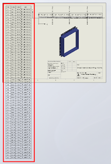
Before we continue, remember that we can only fit so much on to a single sheet before it becomes unreadable, so there is obvioulsy a limit to how many rows you will be able to fit vertically on a specific sheet size.
Click anywhere in the table to activate its properties. You will see this dialogue appear above the table:

Note where the adjustment settings are for Font Size and Vertical Cell Padding. We'll get back to that in a second.
Next, click on the number 2 to select the entire row. Hold down the Shift key and select the last row in your table (I had sixty rows all up in this example). You should now have all rows except the heading row selected. With all rows selected you can change your font size; I have used 9, which is still quite readable and then we want to adjust the Vertical Cell Padding.
You will note though, that when you dial down (using the up-down arrow toggles) you will be stopped at zero. Naturally you will think this to be the limit, but alas, we know with Solidworks anything is possible. Simply select the Vertical Cell Padding field as below...

And while we are at it, quickly click anywhere in the table, then click the black cross to the left of Column A to activate the table properties dialogue, which will appear to the left of your screen. We want to tidy things up a little before printing. In the properties dialogue select "Combine same sizes" and you will get this:

In the properties dialogue, click the green check mark to close and we're done.
You should now have your table fitting nicely onto your drawing sheet and looking much better than when we started.

Have a play with those settings and I hope that this has helped you somewhat to tidy up those Hole Tables.
Pic_1: The Problem

Before we continue, remember that we can only fit so much on to a single sheet before it becomes unreadable, so there is obvioulsy a limit to how many rows you will be able to fit vertically on a specific sheet size.
Click anywhere in the table to activate its properties. You will see this dialogue appear above the table:

Note where the adjustment settings are for Font Size and Vertical Cell Padding. We'll get back to that in a second.
Next, click on the number 2 to select the entire row. Hold down the Shift key and select the last row in your table (I had sixty rows all up in this example). You should now have all rows except the heading row selected. With all rows selected you can change your font size; I have used 9, which is still quite readable and then we want to adjust the Vertical Cell Padding.
You will note though, that when you dial down (using the up-down arrow toggles) you will be stopped at zero. Naturally you will think this to be the limit, but alas, we know with Solidworks anything is possible. Simply select the Vertical Cell Padding field as below...

Type negative 1.8 i.e. -1.8 and hit the Enter key on your keyboard. You should now be looking something like this in the settings dialogue...


and your cell text will be hugging the cell borders all nice and cosy, like this:


And while we are at it, quickly click anywhere in the table, then click the black cross to the left of Column A to activate the table properties dialogue, which will appear to the left of your screen. We want to tidy things up a little before printing. In the properties dialogue select "Combine same sizes" and you will get this:

In the properties dialogue, click the green check mark to close and we're done.
You should now have your table fitting nicely onto your drawing sheet and looking much better than when we started.

Have a play with those settings and I hope that this has helped you somewhat to tidy up those Hole Tables.
Tuesday, October 25, 2011
Text Size driven by Design Table
This is a post that relates to a question I was asked last week on controlling the size of fonts via design tables. My initial answer was "no" as font size cant be controlled via a design table, but after a bit of thought about what the customer was trying to achieve, could a scale feature be controlled? The answer is YES and quite conveniently the answer is located in the SolidWorks help, but I have provided screenshots on the step by step process required.


Step 4.


Step 1.
Create your Word using sketch text and an extrude. Unfortunately sketch scale cant be controlled via a design table so it will need to a feature that is scaled.
Step 2.
Add your scale feature and make sure to select all the letters as bodies. It is not important what is used as the scale origin.
Step 3.
Inserting a design table. Note you must select a parameter such as one of the dimesions used for the layout to get the design table up and running. You dont need to change this parameter, but it does help the auto create option.
Step 4.
Adding the parameter to control the scale which should be "$X_AXIS@scale_feature_name" so in my example the parameter is $x_AXIS@scale1. You can also control the "Y" and "Z" should you choose the scaling not to be uniform.
Step 5.
Exit the table and then edit the table to re-enter of which you should now see your scale size showing in the table.
Step 6.
Change the scale size in the table and now you have a Word size driven by a design table.
I know this post will be useful for one customer and hopefully it aids a few others. Please never be shy of contacting your local Support Engineer with such questions as we are here to help you and enjoy a challenge.
Tuesday, October 11, 2011
How to place a point at the Center of Mass
How to place a point at the Center of Mass of a solid and add reference planes through the point so that they update as the solid changes.
Tuesday, September 27, 2011
Subscribe to:
Posts (Atom)
Hot Posts

Hot Car Girl
